Friday, July 13, 2018

SHEAR FORCE AND BENDING MOMENT DIAGRAM

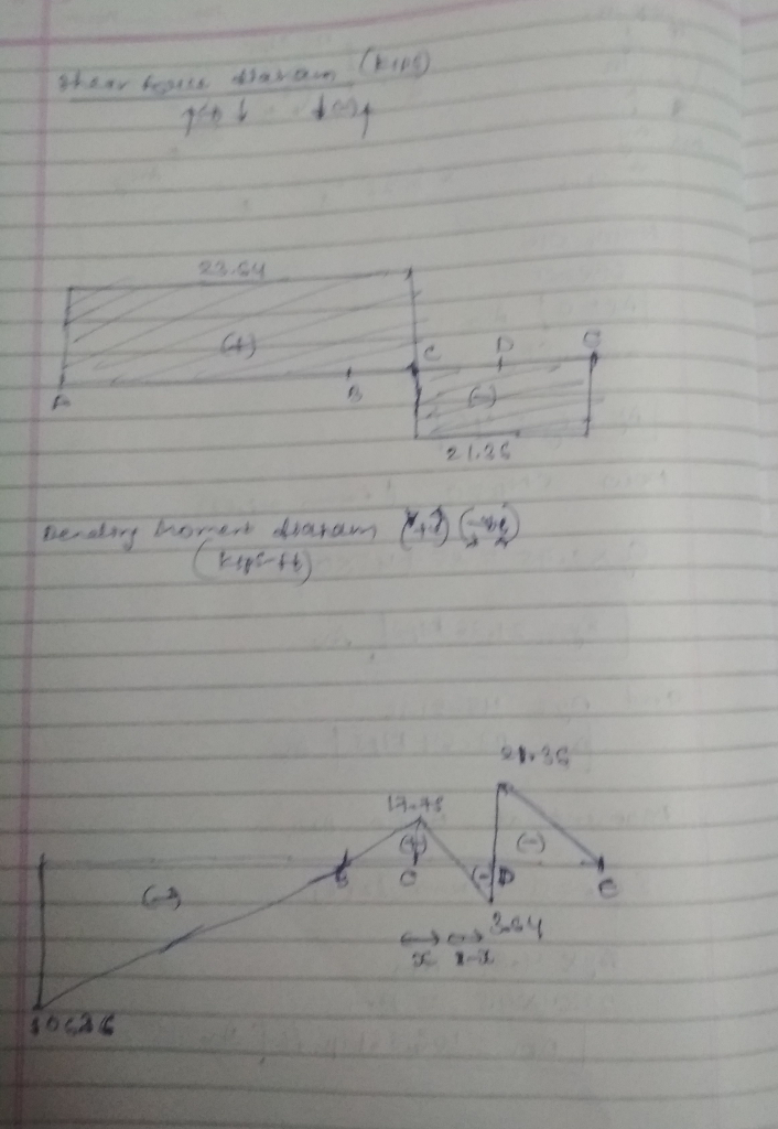
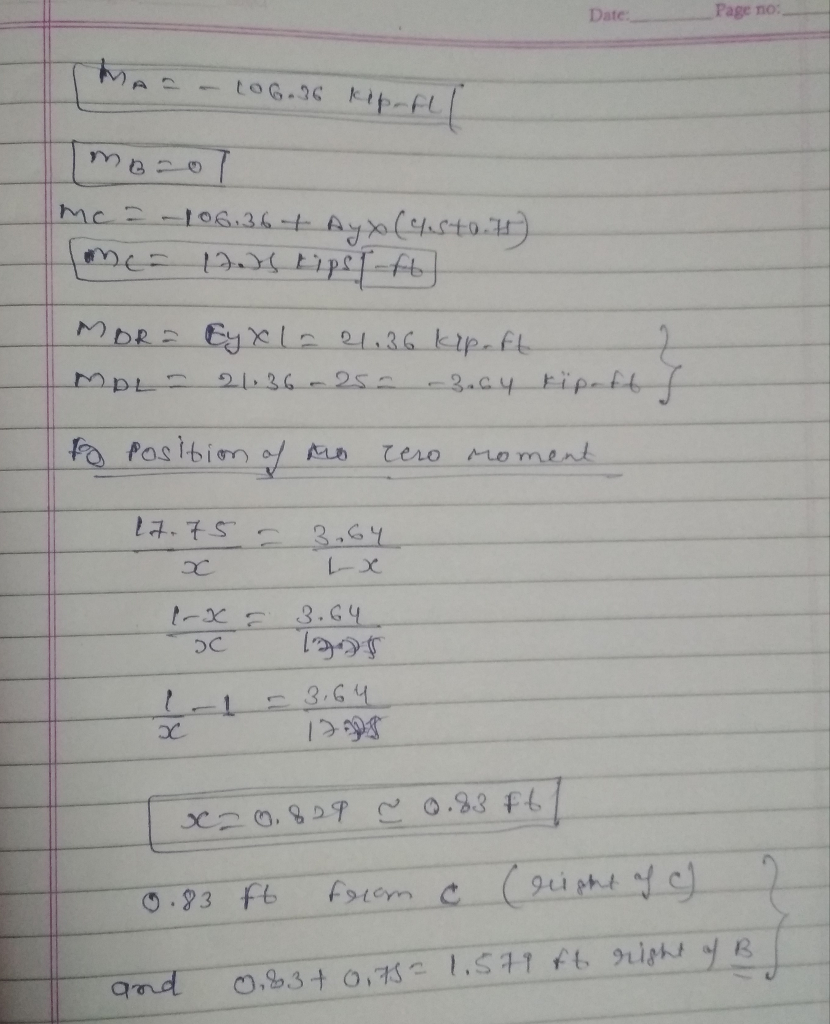
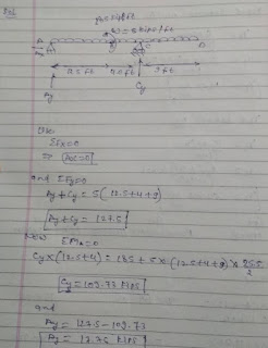
SFD AND BMD


SFD AND BMD


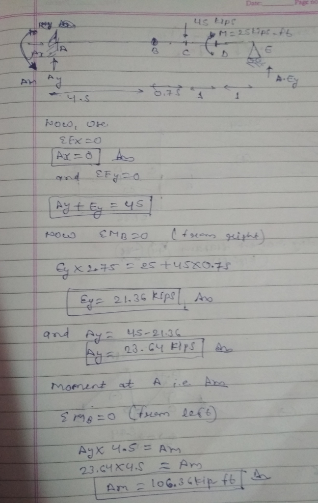
BMD AND SFD OF SIMPLY SUPPORTED OVERHANGING BEAM

P7.21-Use the graphical method to construct the shear-force and bending-moment diagrams for the beams shown in Figures PZ 21 and P122. Label all significant points on each diagram, and identify the maximum P7.22 moments along with their respective locations. In addition, 52 kN 36 kN 35 kN/m ?? 150 kN n 6 m 3 m FIGURE PT.21


SFD AND BMD


BMD AND SFD OF CANTILEVERED BEAM WHERE B IS HINGE
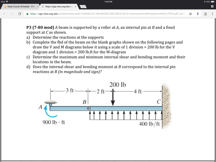
Pad 84%- i: Daly Course Schedule-EN x D httpsluga view usgeduie ? https //uga view usg.edu 1545683-CO.180 ENGR2120E 5387420191 P3 (7-80 mod) A beam is supported by a roller at A, an internal pin at Band a fixed support at C as shown a) Determine the reactions at the supports b) Complete the fbd of the beam on the blank graphs shown on the following pages and 200 lb for the V draw the V and M diagrams below it using a scale of 1 division diagram and 1 division 200 lb.ft for the M-diagram Determine the maximum and minimum internal shear and bending moment and their locations in the beam c) d) Does the internal shear and bending moment at B correspond to the internal pin reactions at B (in magnitude and sign)? 200 lb 3 ft 2 ft 4 ft 900 lb ft 400 lb/ft


SFD AND BMD OF SS BEAM WITH MOMENT ON BEAM
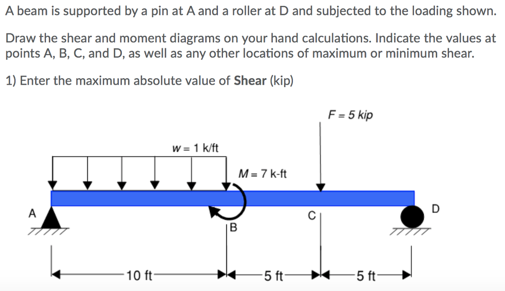
A beam is supported by a pin at A and a roller at D and subjected to the loading shown. Draw the shear and moment diagrams on your hand calculations. Indicate the values at points A, B, C, and D, as well as any other locations of maximum or minimum shear. 1) Enter the maximum absolute value of Shear (kip) F-5 kip W-1 k/ft M- 7 k-ft 10 ft


                                                     BMD AND SFD OF BEAM


SFD AND BMD OF OVERHANGING BEAM WITH UDL 


                                                        BMD AND SFD OF BEAM


                                                        BMD AND SFD OF BEAM


SFD FOR THE BEAM


DRAW AXIAL FORCE, SHEAR FORCE AND BENDING MOMENT DIAGRAM
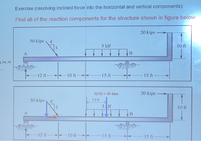
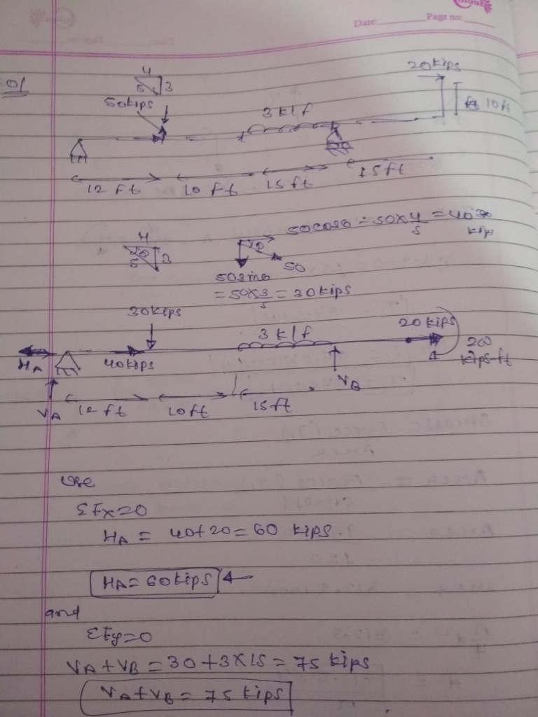
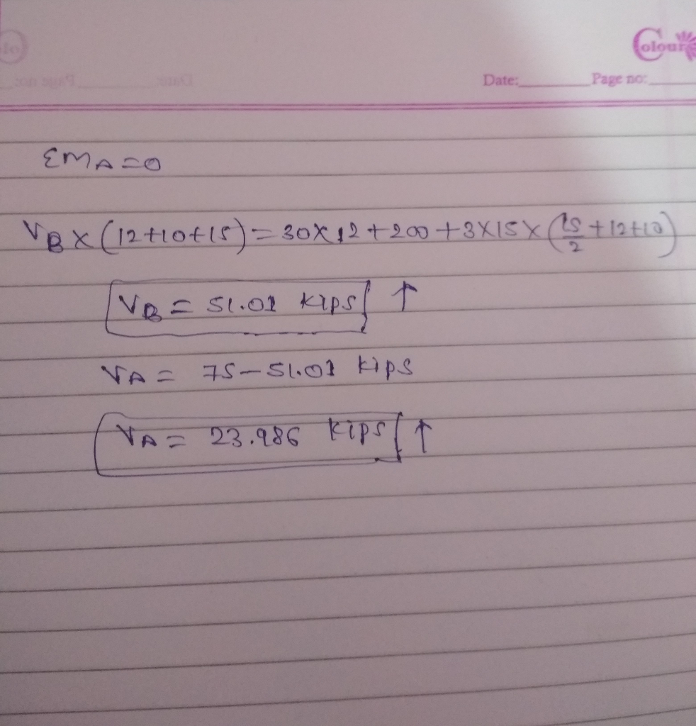
Exercise (resolving inclined force into the horizontal and vertical components): Find all of the reaction components for the structure shown in figure below 20 kips . 50 kips 3 klf 13 ?04-14 12 f 10 20 kips 3(15) = 45 kips 7.5 50 kips 10 f 13 12f 15 15 ft


No comments:

Post a Comment