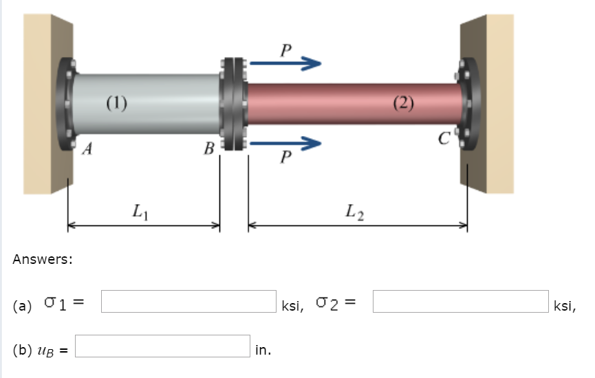
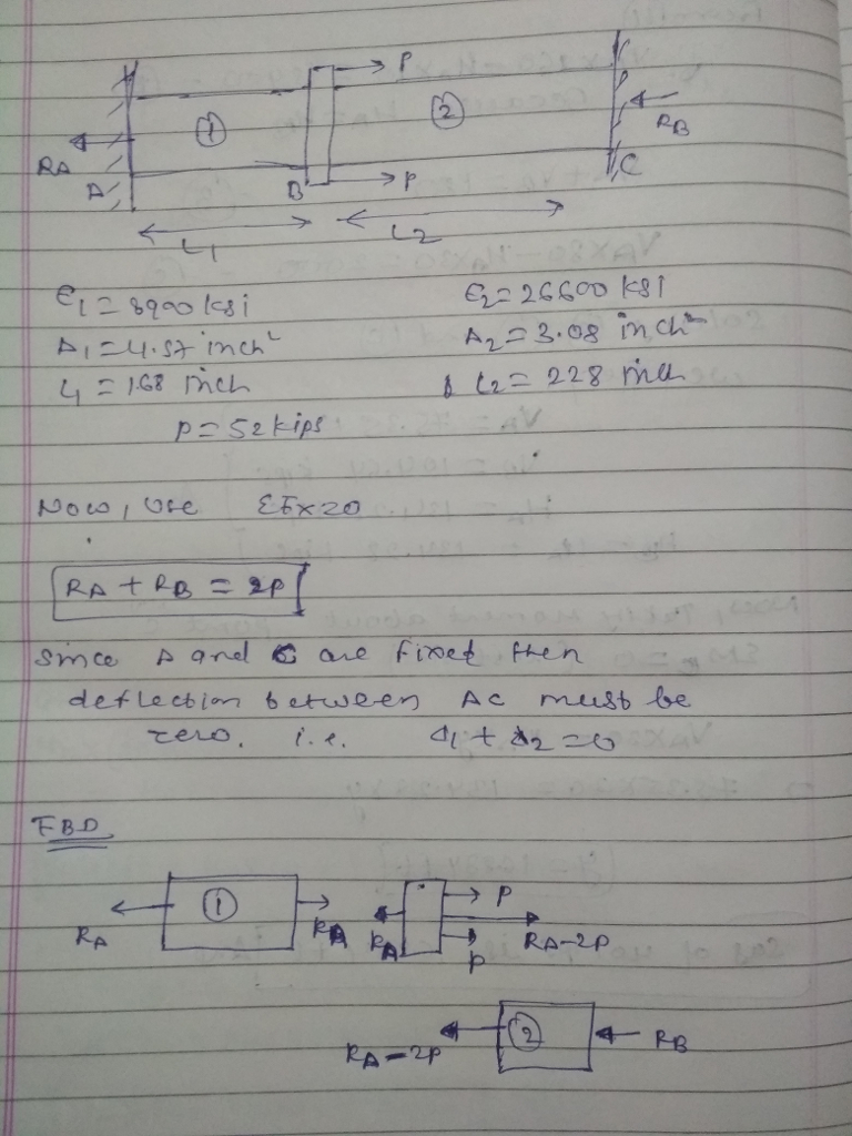
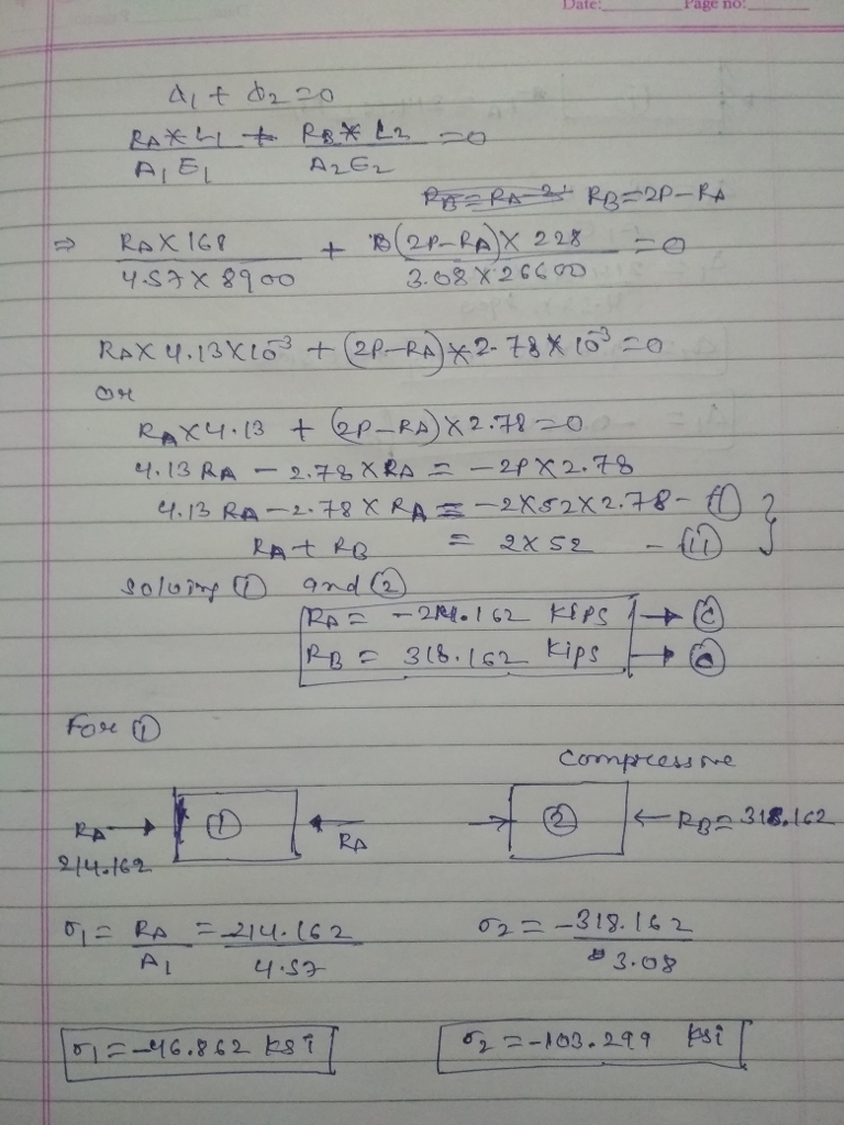
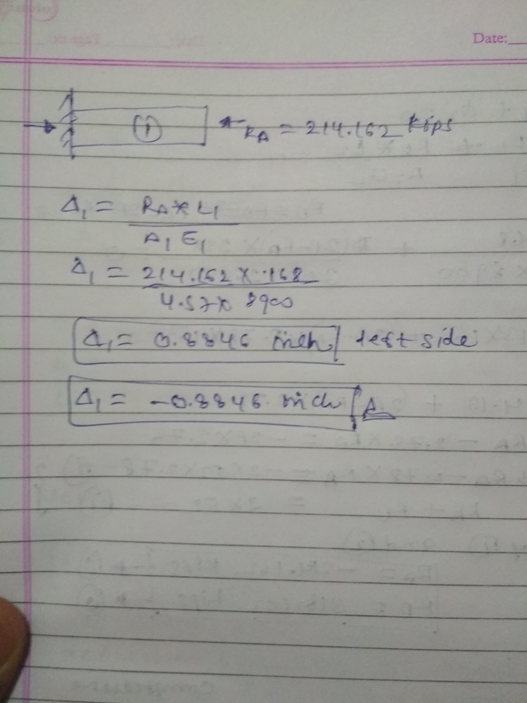
An aluminum alloy [E = 8900 ksi] pipe with a cross-sectional area of A1 = 4.57 in.2 is connected at flange Bto a steel [E = 26600 ksi] pipe with a cross-sectional area of A2 = 3.08 in.2. The assembly is connected to rigid supports at Aand C. Assume L1=168 in., L2=228 in., and P=52 kips. For the loading shown, determine:(a) the normal stresses in aluminum pipe (1) and steel pipe (2) ( ,
,  use positive if tensile, negative if compressive).(b) the deflection uB (use positive if it moves to the right and negative if it moves to the left) of flange B.
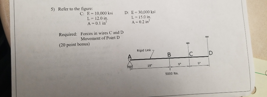
CALCULATE THE FORCE IN THE CABLE C AND D, AND EXTENSION IN CABLE D.
Steps to solve:
- Draw FBD
- Taking moment about A
- Use triangle properties and find relation.
- Now find force in member C and D.
- finally calculate the movement of D using Axial deflection formula.
CALCULATE THE FORCE IN CABLE AT B AND DIAMETER OF CABLE
Steps to solve:
- Draw FBD.
- Taking moment about A.
- find the force in cable B.
- using the force and stress, find the area of cable.
- Finally using area find the diameter of cable.

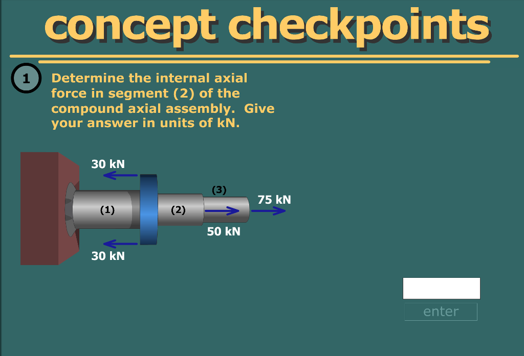
CALCULATE THE INTERNAL FORCE AT SECTION X-X
Steps to solve:
- Draw FBD
- from equilibrium find unknown force F.
- From the FBD find the force at Section X-X
CALCULATE THE HYDRAULIC RETENTION TIME, IF THE VOLUME AND DISCHARGE THROUGH REACTOR IS GIVEN
What is the hydraulic retention time for a factor that has a flow rate of 450 liter per minute and a volume of 32.5m^2
Steps to solve:
- HRT is the ratio of volume of the reactor to the discharge through reactor.
- convert the discharge from litres per day to cumecs.
- now find the HRT
CALCULATE THE BOD OF WASTE WATER 8ml, FOR WHICH INITIAL AND FINAL DO IS GIVEN
Steps to solve:
- Calculate the dilution factor
- Now find BOD.
CALCULATE THE DO OF WATER, WHEN WATER FROM FACTORY AND RIVER IS MIXED
SHOW THAT FOR RECTANGULAR SECTION WIDTH IS TWO TIMES OF DEPTH
Steps to solve:
- find perimeter of section in terms of width and depth.
- Now convert the perimeter in terms of depth only.
- for optimum, perimeter should be minimum.
- for minimum differentiate perimeter with respect to depth(y)
- from the above relation width is 2 times the depth(y)
CALCULATE THE REACTIONS OF THE FRAME
Steps to solve:
- Draw FBD.
- write equilibrium equation in X and Y directions
- Take moment about A.
- Now find the reactions at A and B

CALCULATE THE REACTIONS OF THE FRAME
Steps to solve:
- Draw FBD.
- write equilibrium equation in X and Y directions
- Take moment about A.
- Now find the reactions at A and B

CALCULATE THE REACTIONS OF THE FRAME
Steps to solve:
- Draw FBD.
- write equilibrium equation in X and Y directions
- Take moment about A.
- also take moment about C from left side of C.
- Now calculate the reactions at A and B


CALCULATE THE REACTIONS OF THE FRAME
Steps to solve:
- Draw FBD.
- write equilibrium equation in X and Y directions
- Take moment about A.

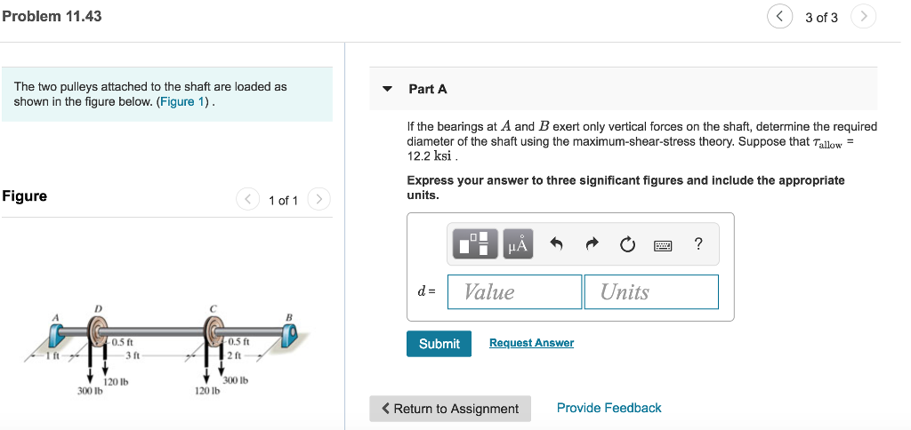
CALCULATE THE DIAMETER OF SOLID SHAFT, IF THE ALLOWABLE STRESS AND APPLIED POWER IS GIVEN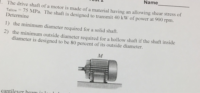
Steps to solve:
- Allowable stress, power and rotation is given
- from power and rotation find torque
- finally find the diameter of shaft

IF THE INTERNAL DIAMETER IS .8 TIMES THE OUTSIDE DIAMETER THEN FIND THE ENTERTAINMENT OF HOLLOW SHAFT
Steps to solve:
- Allowable stress, power and rotation is given
- from power and rotation find torque
- finally find the diameter of shaft

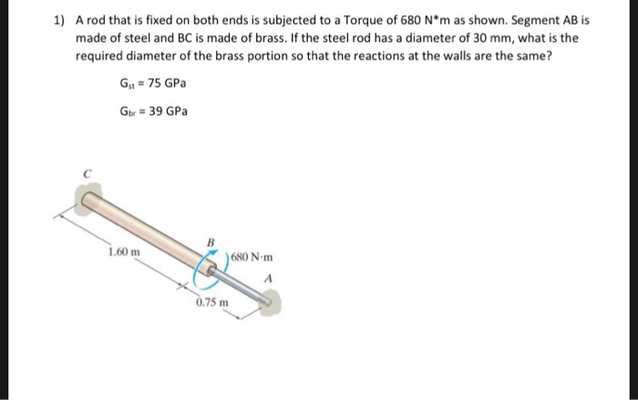
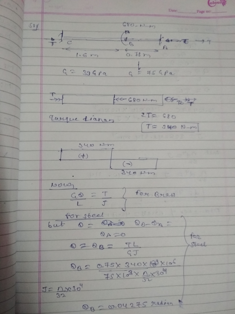
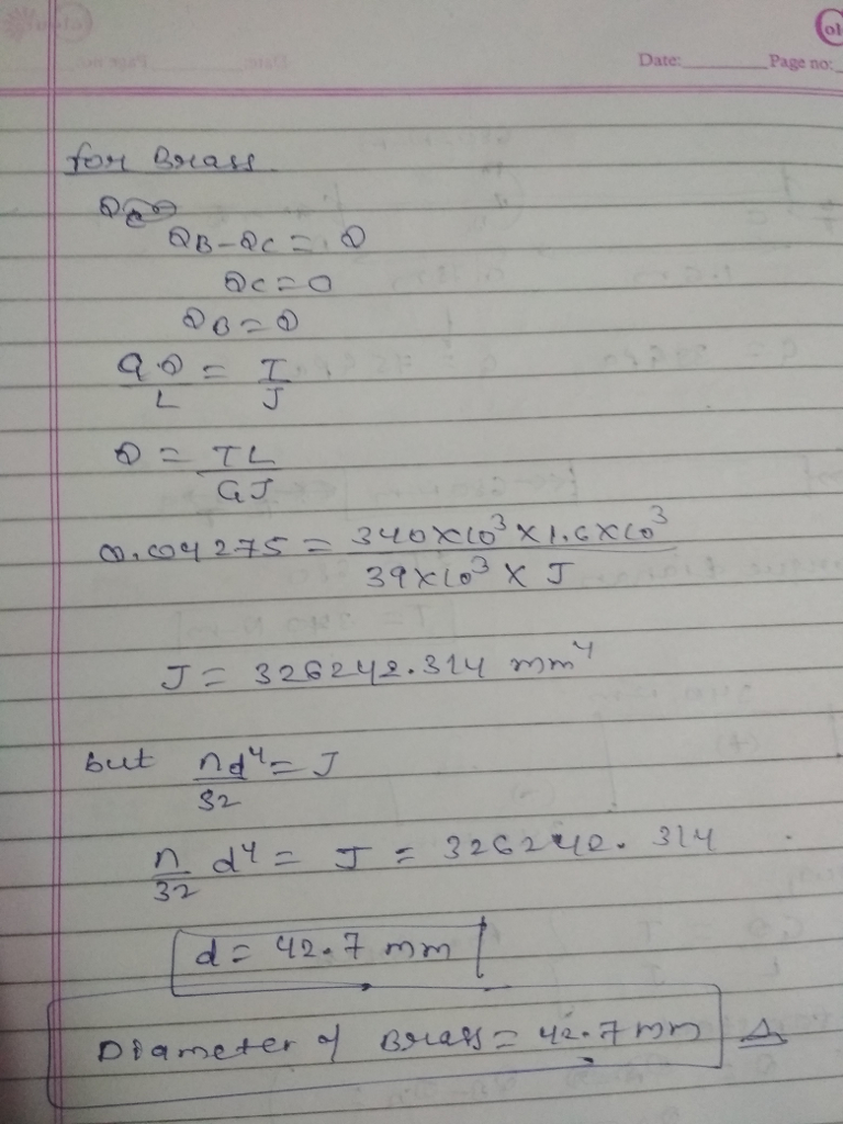
CALCULATE THE DIAMETER OF SHAFT WHEN THE TORSION IS APPLIED
Steps to solve:
- Draw torque diagram in terms of Ta and Tb.
- since A and B are fixed hence rotation will be zero
- From Above relation find Ta
- draw the torque diagram
- Now find the diameter of shaft


CALCULATE THE VALUE OF 'P' AND LENGTH OF SHAFT AB
Steps to solve:
- Draw toque diagram in terms of P
- find polar moment of inertia
- from polar moment of inertia find the torue
- find the P
- find the length AB


CHARACTERISTICS OF ROAD TRANSPORT
CALCULATE THE MAXIMUM DENSITY OF ROAD
CALCULATE THE REACTIONS OF STATICALLY INDETERMINATE BEAM
CALCULATE THE REACTIONS OF STATICALLY INDETERMINATE BEAM
CALCULATE THE REACTIONS OF STATICALLY INDETERMINATE BEAM
CALCULATE THE REACTIONS OF STATICALLY INDETERMINATE BEAM AND AREA OF SECTION 1 AND 2
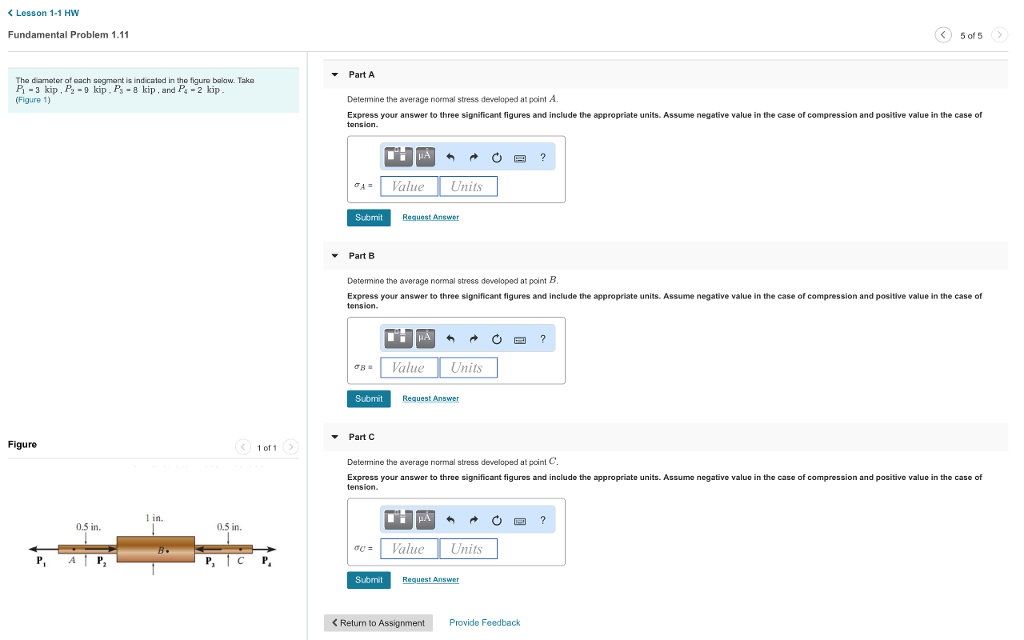
CALCULATE THE STRESS AT POINT A, B AND C
 ,
,  use positive if tensile, negative if compressive).(b) the deflection uB (use positive if it moves to the right and negative if it moves to the left) of flange B.